Cross-section properties may be assigned to members in one of two ways; either by choosing a shape directly from the steel database, or by using a section set. Section sets provide a way to group members so that they have the same properties. Adjusting the set properties, rather than selecting and adjusting each member can achieve changes to the properties for all of the members in the set. You must use section sets if you want to perform timber code checks or steel shape optimization.
The cross section data for the members is recorded on the Section Sets spreadsheet. Cross sectional properties can be entered manually or may be retrieved from one of the shape databases. Currently the databases include Hot Rolled Steel, Cold Formed Steel, Wood, Concrete, and Aluminum. Once the section is defined, it is then referenced on the Members spreadsheet when assigning properties to a member.
To Define a New Section Set
Note:
The Section Sets spreadsheet records the section properties for
the member elements and may be accessed by selecting
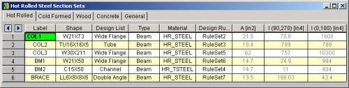
The following are input columns on the spreadsheet that may be used to specify cross section data for the members in the model.
The Section Label is the label you'll reference on the Members spreadsheet to assign properties to a member. This label can be anything you wish, so long as it's not the same as any other section set label.
The Shape field is used to obtain properties from the shape databases.
To use the database, simply enter the name of the database shape and the
shape properties (A, I, J) will be filled in
automatically. Click ![]() to pick from
the database.
to pick from
the database.
If you don't want to use a database shape and wish to enter the shape properties directly, just leave this field blank.
Note:
The Material field is used to enter the label of the material. The material must be defined on the Materials spreadsheet or on the Wood Properties spreadsheet.
Enter the member type for the section set. The choices are Column, Beam, Vertical Brace, and Horizontal Brace.
Here are the main effects that the member type will have on your structure:
Enter the design list type that you wish to use for this section set. This entry will affect the members that are available to program when it is suggesting alternate or optimized shapes. Refer to Design Optimization for more information on the member optimization procedure. Also refer to Appendix A – Redesign Lists for information on creating or editing these lists.
Enter the design rules type that you wish to use for this section set. When the program is checking alternate or optimized shapes, it will restrict its selections to members that obey the chosen design rules. Refer to Design Rules– Size / U.C. for more information.
The cross section properties will be filled in automatically if you use a database shape. For General Materials, you may leave the shape field blank and enter these directly. I(90,270) and Izz(0,180) are for bending about the respective member local axes. The 0, 90, 180 and 270 designations indicate the rotation (in degrees) of the member. If the member has been rotated 90 or 270 degrees the I(90,270) value is used, otherwise the I(0,180) value is used. Note that it's not a good idea to edit these fields if you already have a database shape assigned. Any changes will not be saved and will be replaced with the original values when the file is reopened or the shape is reentered in some other manner. You should create a new shape in the database to avoid this situation.
Note: